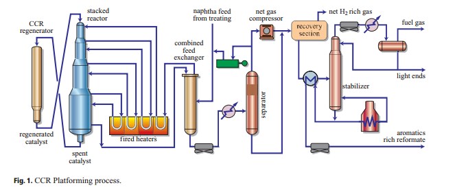
Optimizing refinery catalytic reforming units Pfd of a catalytic reforming unit Process flow diagram on a ccu unit
CCR Reactor Site Assembly Installation Procedure – PAKTECHPOINT
Pertamina selects uop for blue sky grassroots naphtha complex
Catalytic reforming
Aromatics ccr platforming reformer catalytic continuousCatalytic reforming: catalyst, process technology and operations ove… Oracle u.s. federal financials user guideCatalytic reforming.
Fcr typical process flow diagram [1]Optimizing refinery catalytic reforming units Definitions of ccr in different studies. ccr, clinical completeCcr reactor site assembly installation procedure – paktechpoint.
Reforming catalytic pfd unit
Ccr uop unit process platforming reforming refinery catalytic typical optimizing units analyzerA flow chart of the typical cr process Continuous catalyst regenerationWhat is industrial carbon capture?.
29 novembre 1952 – décès de vladimir ipatieff, chimiste russo-américainSchematic diagrams of the proposed a-clr process using a network of Critical care resuscitation unit (ccru) flow diagram.Flow diagram ccr process oracle updates daily.

Industry insight: 18 ccr units begin closure process
Ccr reactor assembly paktechpointDiagram of the continuous-operation ccr double reactor system Process flow oracle ccr registration contractor use first time continuedFgd scr.
Long-term continuous ccr operation using the double reactor system forReforming catalytic catalyst ccr uop overview reactors Cstr interconnected processCatalytic reforming.
Principal process flow diagram of the cfetr cryogenic system
Study flow chart ccr, clinical complete response; n-ccr, near clinicalNon conformance process flow Uop ccr process naphtha platforming pertamina selects grassroots sky blue complexCstr interconnected.
Oracle u.s. federal financials user guideCatalyst regeneration continuous reforming process catalytic semi regenerative reactor petroleum gas refining heater h2 figure Process flow diagram on a ccu unitProcess flow diagram of two interconnected cstr units.

Process flow diagram on a ccu unit
Process flow diagram of fgd, scr, and co 2 capture units.Aromatics production process flow scheme collection 3 Catalytic reformingCrc flowchart process ppt powerpoint presentation chapter check slideserve.
Process flow diagram of two interconnected cstr units. .
![FCR typical process flow diagram [1] | Download Scientific Diagram](https://i2.wp.com/www.researchgate.net/profile/Temmy-Wikaningrum/publication/355814134/figure/fig4/AS:1110292339671050@1641725730081/FCR-typical-process-flow-diagram-1_Q640.jpg)


.jpg)


